


Outdoor Vacuum Circuit Breaker Control Wiring: What EPC Teams Should Verify Before Commissioning
An Outdoor Vacuum Circuit Breaker is ordered months before anyone reads its secondary drawing, and by then the order is fixed. Control voltage, coil type, auxiliary contact count and CT ratio are all locked into the purchase order, and none of them can be corrected on site with a screwdriver. This guide is about the wiring documentation an EPC team should hold before the unit arrives, the values that documentation has to state, and the checks that prove the secondary circuit actually works. Most commissioning delays on an Outdoor VCB are documentation delays.
Outdoor Vacuum Circuit Breaker Control Wiring: EPC Checks
Secondary wiring is the only part of an outdoor VCB that is not type-tested as a system. The interrupter, the insulation and the mechanism are proven by the manufacturer’s routine tests; the control circuit is proven by whoever terminated it. That is why the documentation matters more than the drawing quality — it is the only record of what the circuit is supposed to do.
Six documents belong in the handover pack. If any is missing, ask before the unit ships, not after it is on the pole.
| Document | What It Has To State | Why The EPC Needs It |
|---|---|---|
| Secondary connection diagram | Every core, every terminal number, every device tag | The only drawing a technician can terminate against |
| Terminal block layout | Physical order of terminals inside the cabinet | Turns a schematic into something you can wire |
| Component list | Coil voltages, currents, contact ratings, heater rating | Sizes the battery and proves the coils match site supply |
| Controller manual | Input and output mapping, setting ranges, protocol | Without it the terminal numbers mean nothing |
| Factory secondary test record | Continuity and functional results before shipment | The baseline the site test is compared against |
| Gland plate drawing | Plate dimensions, hole positions, gasket detail | Lets the cable be made off without cutting the plate on site |
Model-Specific Wiring Documents
One family name can hide three different Outdoor VCB Control Wiring schemes, and the differences are not cosmetic. A spring-mechanism ZW32-12 outdoor vacuum circuit breaker has a charging motor, a closing coil, an opening coil and a spring-charge limit switch. A permanent-magnet unit of the same rating replaces all of that with a capacitor bank and a charging module. An intelligent variant adds a controller with binary inputs, CT inputs and a communications port. The terminals are not in the same places, and the schematics are not interchangeable.
So the drawing has to carry the variant code, the sales order number and the unit serial. A drawing without those three is a catalogue drawing, and a catalogue drawing does not bind the factory. Suppliers routinely stamp an unconfigured drawing with a note meaning “for reference only” — if you see that note on a document you intend to terminate against, reject it and ask for the order-specific version. The same applies to revisions: if the factory ships revision B and your site holds revision A, terminal numbers may have moved and nobody will tell you.
Where a family spans voltage classes, get one drawing per rating rather than one drawing with a note. A 40.5 kV ZW7-40.5 pillar-type breaker and a 12 kV unit share a mechanism philosophy but not a cabinet, and the secondary routing differs because the cabinet does.
Terminal, Coil, And Control Power Data
Control voltage is a purchasing decision, and the manufacturers’ own paperwork says so. BYYOU’s ordering instructions for the ZW32 series list five mandatory items, and item three is “the model, name, operating voltage and release type of the equipped operating mechanism”. If it is not on the order, it is not on the unit, and no amount of site work will change a 110 V coil into a 220 V one.
The common set is DC 220 V, DC 110 V, DC 48 V, DC 24 V and AC 220 V. Substation-fed units take the station battery at DC 110 V or 220 V. Pole-mounted units on a local battery, or on a solar-plus-battery supply, often run DC 24 V, which changes the coil current by an order of magnitude and therefore the cable cross-section. The Outdoor VCB Wiring Diagram has to state which one, and the component list has to state the coil current at that voltage.
Two timing figures matter more than most commissioning engineers expect. The first is the minimum command time for the release coils: on a 36 kV outdoor breaker of the EOFVp-36 type it is 20 ms, so a test set that emits a 10 ms pulse will appear to fail a perfectly healthy breaker. The second is the motor charging time, quoted as 20 s or less on the same unit. If charging takes materially longer on site than it did in the factory report, the motor supply is sagging or the mechanism is stiff, and both are worth finding before energisation rather than after.
Coils are short-time rated. A closing coil or a shunt trip is designed for a pulse measured in tens of milliseconds, not for continuous energisation. Where a controller provides a latching output and the wiring uses it to hold the close command, the coil will overheat and eventually fail open — and it will do so months after commissioning, which is the worst possible time to diagnose it.

The control cabinet is where the EPC’s scope meets the factory’s: controller, terminal block, secondary cable and the wiring label the technician will actually work from.
A permanent-magnet mechanism deserves its own paragraph because it fails differently. Its stored energy is in a capacitor, not a spring. The breaker will not close if that capacitor is not charged, even with healthy control power, a healthy coil and a correct command. On a unit that has sat in storage for a year, the charging module or the capacitor is the first thing to check when a close command does nothing, and the commissioning record should carry the capacitor charge time and the voltage reached, not just a tick in a box.
Protection And Remote-Control Interfaces
The current transformer interface is where a small documentation error becomes a large protection error. A CT secondary is 5 A or 1 A, and the controller’s ratio setting has to match the physical CT, not the CT the design originally specified. A ratio set to 200/5 on a 400/5 transformer halves every current the relay sees, which doubles every operating threshold. Polarity matters as much: with P1 facing the busbar, S1 goes to the controller’s polarity terminal, and one phase reversed inverts the residual current so that a directional earth-fault element operates in the wrong direction. That fault trips healthy feeders.
Binary inputs need a stated wetting arrangement on any Outdoor VCB with a controller. Position, spring charged, gas pressure where the design has it, remote/local and external trip each need to be defined as wet or dry, and at what voltage. A dry input wired to a wet output reads “active” permanently; a wet input wired to a dry contact never reads at all. Both look like a controller fault and neither is one.
Remote control needs a provable interlock, not a documented one. The local/remote selector must be demonstrated to block a remote close command while it is in local, with the control room watching the point on their screen. That single test is what an authorised person will rely on for the next twenty years.
Communications are usually RS485 on twisted pair, running Modbus RTU or IEC 60870-5-103, with GPRS or 4G where there is no fibre. Three details decide whether it works: the shield is earthed at one end only, the termination resistor sits at the far end of the bus rather than at each device, and the baud rate and parity match the master. The document that makes all of this commissionable is a point-to-terminal mapping table, listing every point, its terminal, its normal state and its alarm text, signed by the EPC and accepted by the utility. Without it, point-to-point testing becomes a phone call in which two people describe the same terminal differently.
Auxiliary Contacts And Position Signals
Auxiliary contacts are the interface between the breaker and everything that needs to know what the breaker is doing. The convention is 52a for a contact closed when the breaker is closed, and 52b for one closed when it is open. Outdoor units commonly offer four of each or two of each, and the count is an ordering option, so it belongs on the drawing rather than in an email.
The distinction that matters at commissioning is between a mechanical auxiliary contact and a controller-generated position signal. A 52b wired into a trip or interlock circuit must be driven by the operating shaft. If it is synthesised by the controller instead, then a controller failure removes the trip path at exactly the moment the trip path is needed. Where a controller signal is used for indication only, say so on the drawing, because the next engineer will otherwise assume it carries the same authority as the mechanical contact.
Contact rating is the second trap. An auxiliary contact rated for control duty may not switch reliably at the low current a 24 V PLC input draws — a few milliamps is well below the minimum current that keeps the contact film broken down. The symptom is an indication that is correct in the workshop and intermittent in service, worse in humid weather. Gold-flashed contacts, or a wetting voltage, solve it; more careful termination does not.
Finally, the mechanical flag on the front of the unit is a claim and the auxiliary contact is a signal, and they have to agree. Verify by operating the breaker, not by looking at it. The same discipline applies to the stored-energy indicator, which is worth reading on any unit with a spring mechanism — telling open from closed on a vacuum unit is harder than it looks once the paint has faded.
Pre-Commissioning Wiring Verification
The tests below are the ones that find real defects. They are listed with a criterion because a test without one produces a number rather than a result.
| Check | Method | Pass Criterion |
|---|---|---|
| Control circuit insulation | 500 V megger, electronics disconnected | 2 MΩ or more to earth |
| Core continuity | Point to point against the drawing | Every core proven at both ends |
| Spring charging | Energise motor circuit, time it | 20 s or less, motor cuts out on limit switch |
| Close and trip operation | Pulse the coils, at rated voltage | Pulse at least 20 ms, correct indication after each |
| Reduced voltage operation | Close at 85%, trip at 70% of nominal | Operates without hesitation, battery holds up |
| Anti-pumping | Hold close command on during a trip | Closes once, trips, stays open |
| CT ratio and polarity | Primary injection or secondary injection with polarity check | Ratio matches setting, all phases same direction |
| Protection settings | Secondary injection against the approved file | Operates within tolerance of the approved values |
Trip, Close, And Energy Storage Circuits
Start the Outdoor VCB Control Wiring checks with insulation resistance, and disconnect the controller first. A 500 V megger applied to a 24 V input card destroys it, and the resulting “controller failure” is caused by the test rather than found by it. With the electronics isolated, the criterion for the control circuit is 2 MΩ or more to earth at 500 V; main circuit values are a different test at a different voltage and should not be conflated with it.
Continuity comes next, core by core, against the drawing rather than against the last unit somebody commissioned. Then the functional sequence, in the order the mechanism actually works: charge, close, re-charge, trip, then a trip-free test. On a spring mechanism the closing springs discharge when the breaker closes and the motor immediately recharges them, cutting out on the limit switch. Watch for that re-charge. A unit that closes and then sits discharged will close once and never again, and the cause is usually a motor supply taken from a circuit that is isolated with the trip supply.
Reduced-voltage operation is the test that proves the battery rather than the breaker. A battery at the end of its life reads nominal on open circuit and collapses under a coil pulse. Closing at 85% and tripping at 70% of nominal, with the coil current monitored, separates a healthy supply from one that will fail on the first real fault. Record the voltages at which each operation succeeded; a unit that only just operates at 70% is telling you the battery has months left.
Anti-pumping and trip-free are separate tests and both are required. Anti-pumping means that a close command held on while a trip persists produces one close and one trip, not a series of them; it is a standard requirement for circuit breakers and it is proven by holding the command, not by trusting the wiring. Trip-free means the breaker opens on a trip even while a close command is still applied. Both are quick, both are frequently skipped, and both are the reason a breaker survives a fault that re-strikes.
Cable Entry And Terminal Identification
The gland plate is part of the enclosure, and treating it as an accessory is how an IP54 cabinet becomes an unrated one. The correct sequence, as the manufacturers’ own erection instructions put it, is to dismantle the plate, make a hole sized for the gland actually being used, pass the cable through, seal the plate, and reassemble it with its gasket. An unused hole left open, or a plate refitted without its gasket, cancels the rating on the nameplate no matter what the nameplate says.
Leave enough cable inside the cabinet to reach the terminals without pulling. A cable made off short will be terminated under tension, and a terminal under tension works loose over a few hundred thermal cycles. That is the most common origin of the “random” trip that nobody can reproduce: a screw that was tight at commissioning and is not tight two winters later. Torque every terminal with a calibrated driver to the manufacturer’s figure and record the figure, because “tight” is not a measurement.
Ferrule both ends, and make the ferrule match the drawing rather than the electrician’s shorthand. One core per terminal unless the terminal is rated for more, and no shared terminal between two circuits that could be isolated separately. Signal cables get their screen earthed at one end only; earthing both ends creates a loop that carries circulating current and produces the kind of communications dropout that only appears when a nearby load switches.
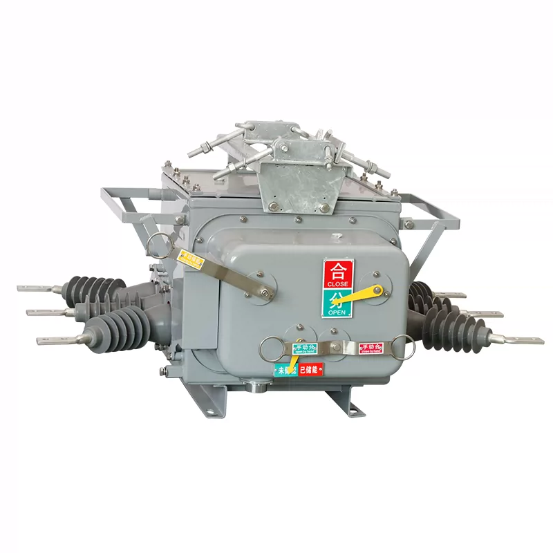
Local controls on an outdoor unit: close and open buttons, the open and closed indicators, and the stored-energy flag a technician reads before touching anything.
One circuit deserves separate attention because it is wired by the EPC and forgotten by everyone: the anti-condensation heater. An outdoor cabinet needs it, and a heater fed permanently from a DC 24 V battery without a thermostat will flatten that battery in days. Check that the heater is thermostat-controlled, that its supply is separate from the trip supply, and that its rating is on the component list so the battery sizing accounted for it.
Approved Test And Verification Records
A commissioning record that says “checked, OK” is not a record. Every line needs a value, a criterion and a signature, and the criterion is the field that is almost always missing. The set that a utility will ask for is short: insulation resistance per circuit, continuity per core, a functional record per function, the protection settings file signed against the approved values, the CT test, the SCADA point-to-point signed by the control room, and a red-lined as-built drawing.
Red-line the drawing on site, on the day, not from memory a week later. The as-built is the document the next crew works from, and the next crew will not know which terminal was moved. The manufacturer’s commissioning list is a reasonable minimum to check your own against: clean the insulating parts, operate the breaker both mechanically and electrically, confirm every indicator including charged and discharged, check for loose connections, and measure insulation resistance.
For the wider sequence around this work — civil, earthing, high-voltage tests and the order they should run in — the step-by-step HV switchgear installation sequence covers the parts that come before and after the secondary circuit.
Get The Wiring Pack Before The Unit Ships
Tell BYYOU the control voltage, coil type, auxiliary contact count and CT ratio, and we will issue the order-specific secondary diagram, terminal layout, component list and factory test record with the unit — not a catalogue drawing that leaves the EPC to guess.
Common Wiring Documentation Errors
These Outdoor VCB wiring errors cost the most site time, in rough order of how often they appear. Most are documentation errors rather than workmanship errors, which is why they are cheap to prevent and expensive to find.
| Error | How It Shows Up | Prevention |
|---|---|---|
| Catalogue drawing instead of an order-specific one | Terminal numbers do not match the cabinet | Require order number and serial on the drawing |
| Control voltage mismatch | Coils buzz, chatter or do nothing at all | State voltage on the order, verify on the nameplate |
| Close or trip coil held energised | Coil fails months later, not at commissioning | Use a momentary output, check latching logic |
| 52a and 52b transposed | Indication inverted, interlocks defeated | Prove both by operating, not by continuity |
| CT ratio or polarity wrong | Thresholds scaled wrongly, directional element reversed | Inject primary or secondary and verify per phase |
| RS485 shield earthed at both ends | Comms drop out when adjacent plant switches | Earth one end, terminate at the far end |
| Auxiliary contact below its minimum current | Indication intermittent, worse in humid weather | Specify gold-flashed contacts or a wetting voltage |
| Heater on the battery without a thermostat | Battery flat within days, unit dead on arrival at the fault | Thermostat control and a separate supply |
Two further errors do not fit in the table because they are process failures rather than wiring failures. The first is an unsupervised trip circuit: nobody proves that the trip path is intact end to end, and the break is discovered when a fault is not cleared. Supervision, or a commissioning injection through the whole path, is the only defence. The second is a drawing that was never red-lined, which turns a correct installation into an incorrect document and sends the next crew to the wrong terminal with complete confidence.
When the symptom is a trip that has already happened rather than a wiring question, the diagnostic sequence in trip fault analysis and treatment picks up where the wiring checks stop, and the instrument set for the wider substation is covered in testing and troubleshooting a compact substation.
Frequently Asked Questions
What Control Voltage Does An Outdoor VCB Need?
Most use DC 220 V or DC 110 V for the trip and close coils, with AC or DC 220 V for the spring-charge motor. Pole-mounted units on a local battery often run DC 24 V.
Can A VCB Be Operated Manually Without Control Power?
Yes. Spring and permanent-magnet units have a manual charging handle plus manual close and trip buttons, so they operate with no auxiliary supply. Protection is dead, so treat it as an emergency.
What Should Buyers Verify Before Ordering An Outdoor VCB Breaker?
Fix control voltage, coil type, auxiliary contact count and CT ratio on the order, and ask for the order-specific wiring diagram and factory secondary test record before you release it.
Conclusion
The wiring is the part of an Outdoor VCB Breaker that no type test covers, because every project wires it differently. What can be controlled is the documentation: an order-specific Outdoor VCB Wiring Diagram, a stated control voltage, a component list with coil data, and a signed record of what was measured. An EPC team that holds those four things before the unit arrives commissions in days. A team that discovers them on site commissions in weeks, and usually discovers the control voltage mismatch first. Neither outcome is decided by the breaker.
Talk To The Team That Builds The Secondary
BYYOU manufactures 12 kV, 24 kV and 40.5 kV outdoor vacuum circuit breakers on spring, permanent-magnet and intelligent-controller platforms, with OEM and ODM support for utilities, EPCs and panel builders. Send us your single line diagram and we will confirm the control scheme before the order is placed.
Related Resources
- A Complete Guide To Vacuum Circuit Breaker (VCB)
- What Is An Outdoor Vacuum Circuit Breaker: Outdoor VCB VS Indoor VCB
- A Deep Dive Into Vacuum Circuit Breaker Parts
- Choosing Between Pole-Mounted And Ground-Mounted Outdoor Vacuum Circuit Breakers
- 11kV VS 33kV VS 40.5kV Outdoor Vacuum Circuit Breakers: Which One Is Best
- Outdoor Vacuum Circuit Breaker Buying Guide For Electrical Contractors
- How To Extend The Service Life Of Outdoor Vacuum Circuit Breakers


