GCS Low Voltage Draw Out Switchgear | BYYOU ...
GCS Low Voltage Draw Out Switchgear

GCS Low Voltage Draw Out Switchgear


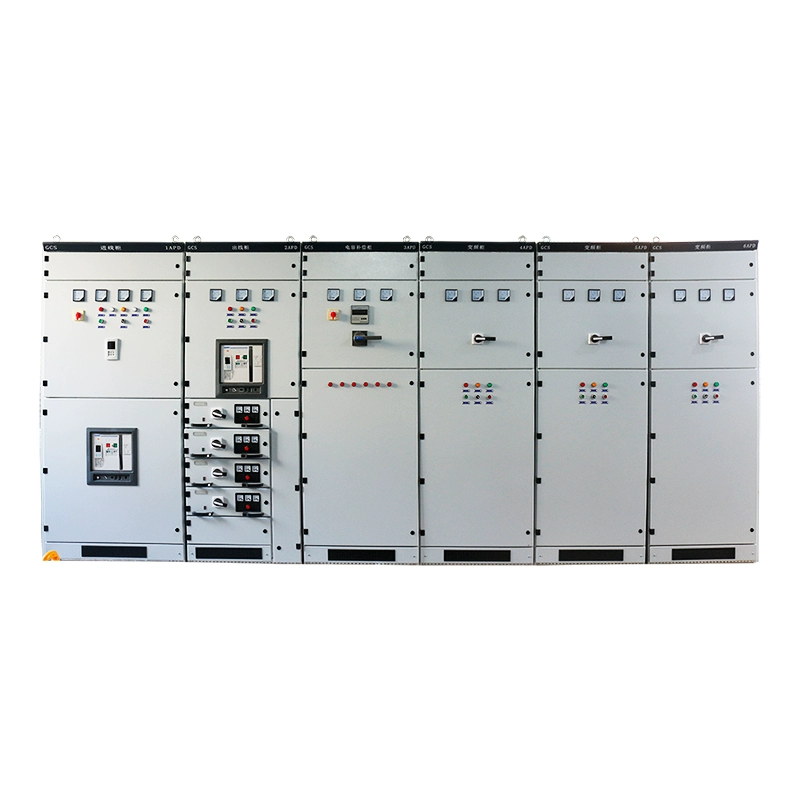
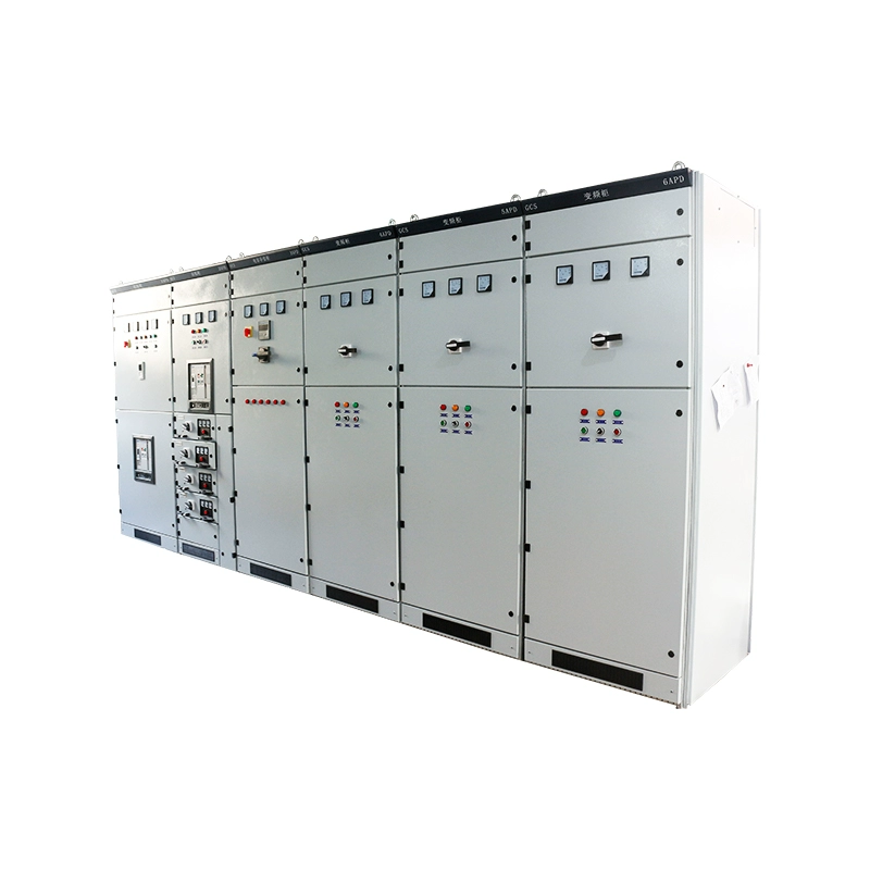
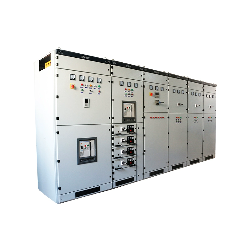
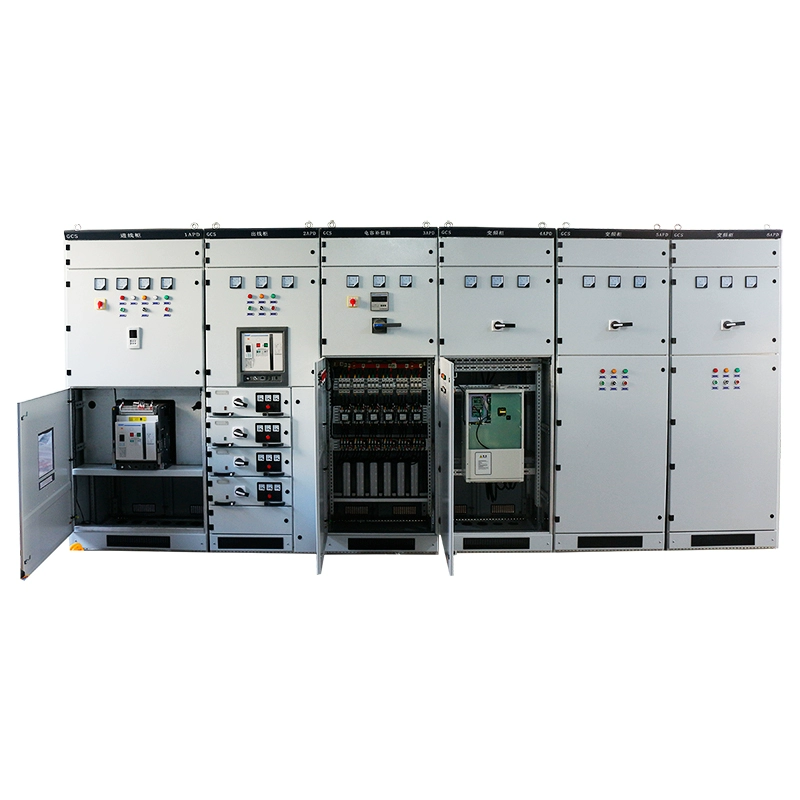
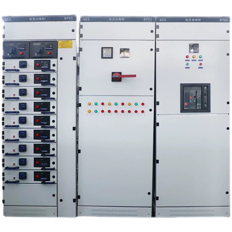
GCS low voltage draw out switchgear features removable functional units for safe, live-maintenance access. Perfect for oil, chemical, and power generation facilities where uptime and operational flexibility are critical.

GCS Low Voltage Switchgear is a compact, low-voltage distribution solution rated at 4000A, 380-660V, 50/60Hz. Designed for power plants and petrochemical systems requiring high automation and computer interface compatibility.

[email protected] Inquiry Now
Product Introduction
Drawing And Size

GCS low voltage switchgear are suitable for power distribution systems in power plants, petroleum, chemical, metallurgy, textile, high-rise buildings and other industries. In large power plants, petrochemical systems and other places with a high degree of automation that require interfaces with computers, as a three-phase AC frequency of 50 (60) Hz, rated working voltage of 380V (400V), (660V), rated electric sulfur of 4000A and The following low-voltage complete power distribution devices are used for power distribution, motor centralized control, and reactive power compensation in the power generation and power supply systems.

This product complies with: GB7251.12-2013 “Low-voltage complete drawout switchgear and control equipment” professional standard.


Item Meaning:

GCS Low Voltage Draw Out Switchgear Item Meaning


GCS Switchgear Features:

  • Increase the thermal capacity of the adapter, and greatly reduce the additional temperature rise caused by the temperature rise of the adapter to the connector, cable head, and partition plate.
  • The separation between functional units and compartments is clear and reliable, and the failure of one unit will not affect the work of other units, so that the failure is limited to the minimum range.
  • The horizontal arrangement of the busbars makes the device have good dynamic and thermal stability and can withstand the impact of 80/176kA short-circuit current.
  • The number of circuits in a single MCC cabinet is up to 22, which fully considers the needs of large single-machine passenger power generation, petrochemical systems and other industries for automated motor groups.
  • The connection between the device and the external cables is completed in the cable compartment, and the cables can go in and out up and down. The current transformer is installed in the cable compartment to facilitate installation and maintenance.
  • The same power distribution system can escape the matching of current-limiting reactors to limit short-circuit current, stabilize the bus voltage at a certain value, and partially reduce the requirements for short-circuit strength of components.
  • The drawer unit has a sufficient number of secondary connectors (32 pairs for 1 unit and above, 20 pairs for 1/2 unit, which can meet the requirements for the number of connection points of computer interface and automatic control circuit.

GCS Low Voltage Draw Out Switchgear
Auxiliary Circuit:

The design of the auxiliary circuit diagram conforms to the relevant design technical regulations such as the “Technical Regulations for Power Design of Thermal Power Plants”, and is suitable for low-voltage power supply systems of power plants and substations, and low-voltage power distribution systems in factories, mines, and high-rise buildings.

The auxiliary circuit scheme is designed according to the main circuit scheme by dividing the functional units of the power incoming line, feeder (PC) and motor feeder (MCC) operation control.


Technical Parameters:

GCS Low Voltage Switchgear Technical Parameters


Ordering Instructions:

The contract should include:

  • The full model of the product includes the scheme number of the main circuit and the scheme number of the auxiliary circuit
  • Combination sequence diagram of the main circuit system
  • Electrical schematic diagram of auxiliary circuit
  • List of components in the cabinet
  • Setting parameters such as voltage, current and time in the circuit
  • Other special requirements inconsistent with the normal use of the product

Low Voltage Switchgear Related Products

Installation Diagram:
GCS Switchgear Installation Diagram

PT Cabinet Installation Diagram:

PT Cabinet Installation DiagramMCC Cabinet Installation Diagram:

MCC Cabinet Installation Diagram

Hot Products
we are committed to continuously improving and expanding our product offerings to cater to ever-changing market demands. Our best-selling products are a testament to our dedication to quality, innovation, and customer satisfaction.
×
Seraphinite AcceleratorOptimized by Seraphinite Accelerator
Turns on site high speed to be attractive for people and search engines.